
What Is A FIR Filter?
The use of FIR filters (or finite impulse response filters) has grown in popularity in the live sound world as digital signal processing (DSP) for loudspeakers becomes more and more sophisticated. While not a new technology in itself, these filters provide a powerful tool in system optimization due to their linear phase properties. But what exactly do we mean by “finite impulse response” and how do these filters work? In order to understand digital signal processing better we are going to need to take a step back into our understanding of mathematics and levels of abstraction.
A (Very) Brief Intro To DSP
One of the reasons I find mathematics so awesome is because we are able to take values in the real or imaginary world and represent them either symbolically or as a variable in order to analyze them. We can use the number “2” to represent two physical oranges or apples. Similarly, we can take it up another level of abstraction by saying we have “x” amount of oranges or apples to represent a variable amount of said item. Let’s say we wanted to describe an increasing amount of apples where for every new index of apples, we add the sum of the previous number of apples. We can write this as an arithmetic series for all positive integer number “n” of apples as:

Where for each index of apples starting at 1, 2, 3, 4…etc onto infinity we have the current index value n plus the sum of all the values before it. Ok, you might be asking yourself why we are talking about apples when we are supposed to be talking about FIR filters. Well, the reason is that digital signal processing can be represented using this series notation and it makes it a lot easier than writing out the value for every single input into a filter. If we were to sample a sine wave like the one below, we could express the total number of samples over the period from t1 to t2 as the sum of all the samples over that given period.

In fact, as Lyons points out in Understanding Digital Signal Processing (2011) we can express the discrete-time sequence for a given sine-wave at frequency f (in Hertz) at a given time t (in seconds) with the function f(n) =

This equation allows us to translate each value of the sine wave, for example, voltage in an electric signal, for a discrete moment in time into an integer value that can be plotted in digital form.

What our brain wants to do is draw lines in between these values to create a continuous waveform so it looks like the original continuous sine wave that we sampled. In fact, this is not possible because each of these integers are discrete values and thus must be seen separately as compared to an analog, continuous signal. Now, what if the waveform that we sampled wasn’t a perfect sine wave, but instead had peaks and transient values? The nature of FIR filters has the ability to “smooth out” these stray values with linear phase properties.
How It Works
The finite impulse response filter gets its name because the same number, or finite, input values you get going into the filter, you get coming out the output. In Understanding Digital Signal Processing, Lyons uses a great analogy of how FIR filters average out summations like averaging the number of cars crossing over a bridge [2]. If you counted the number of cars going over a bridge every minute and then took an average over the last five minutes of the total number of cars, this averaging has the effect of smoothing out the outlying higher or lower number of vehicles to create a more steady average over time. FIR filters function similarly by taking each input sample and multiplying it by the filter’s coefficients and then summing them at the filter’s output. Lyons points out how this can be described as a series which illustrates the convolution equation for a general “M-tap FIR filter” [3]:

While this may look scary at first, remember from the discussion at the beginning of this blog that mathematical symbols package concepts into something more succinct for us to analyze. What this series is saying is that for every sample value x whose index value is n-k, k being some integer greater than zero, we multiply its value times the coefficient h(k) and sum the values for the number of taps in the filter (M-1). So here’s where things start to get interesting: the filter coefficients h(k) are the FIR filter’s impulse response. Without going too far down the rabbit hole in discussing convolution and different types of FIR windows for filter design, let’s jump into the phase properties of these filters then focus on their applications.
The major advantage of the FIR filter compared to other filters such as the IIR (or infinite impulse response) filter lies in the symmetrical nature of the delay introduced into the signal that doesn’t introduce phase shift into the output of the system. As Lyons points out this relates to the group delay of the system:
When the group delay is constant, as it is over the passband of all FIR filters having symmetrical coefficients, all frequency components of the filter input signal are delayed by an equal amount of time […] before they reach the filter’s output. This means that no phase distortion is induced in the filter’s desired output signal […] [4]
It is well known that phase shift, especially at different frequency ranges, can cause detrimental constructive and/or destructive effects between two signals. Having a filter at your disposal that allows gain and attenuation without introducing phase shift has significant advantages especially when used as a way of optimizing frequency response between zones of loudspeaker cabinets in line arrays. So now that we have talked about what a FIR filter is and its benefits, let’s discuss a case for the application of FIR filters.
Applications of FIR filters
Before sophisticated DSP and processors were so readily available, a common tactic of handling multiway sound systems, particularly line arrays, with problematic high-frequencies was to go up to the amplifier of the offending zone of boxes and physically turn down the amplifier running the HF drivers. I’m not going to argue against doing what you have to do to save people’s ears in dire situations, but the problem with this method is that when you change the gain of the amplifier for the HF in a multiway loudspeaker, you effectively change the crossover point as well. One of our goals in optimizing a sound system is to maintain the isophasic response of the array throughout all the elements and zones of the system. By using FIR filters to adjust the frequency response of a system, we can make adjustments and “smooth out” the summation effects of the interelement angles between loudspeaker cabinets without introducing phase shift in-between zones of our line array.
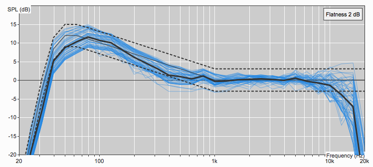
Remember the example Lyons gave comparing the averaging effects of FIR filters to averaging the number of cars crossing a bridge? Now instead of cars, imagine we are trying to “average” out the outlier values for a given frequency band in the high-frequency range of different zones in our line array. These variances are due to the summation effects dependent on the interelement angles between cabinets. Figure A depicts a 16 box large-format line array with only optimized interelement angles between boxes using L-Acoustics’ loudspeaker prediction software Soundvision.

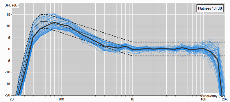
Each blue line represents a measurement of the frequency response along the coverage area of the array. Notice the high amount of variance in frequency response particularly above 8kHz between the boxes across the target audience area for each loudspeaker. Now when we use FIR filtering available in the amplifier controllers and implemented via Network Manager to smooth out these variances like in the car analogy, we get a smoother response closer to the target curve above 8kHz as seen in Figure B.

In this example, FIR filtering allows us to essentially apply EQ to individual zones of boxes within the array without introducing a relative phase shift that would break the isophasic response of the entire array.
Unfortunately, there is still no such thing as a free lunch. What you win in phase coherence, you pay for in propagation time. That is why, sadly, FIR filters aren’t very practical for lower frequency ranges in live sound because the amount of introduced delay at those frequency ranges would not be practical in real-time applications.
Conclusion
By taking discrete samples of a signal in time and representing it with a series expressions, we are able to define filters in digital signal processing as manipulations of a function. Finite impulse response filters with symmetric coefficients are able to smooth out variances in the input signal due to the averaging nature of the filter’s summation. The added advantage here is that this happens without introducing phase distortion, which makes the FIR filter a handy tool for optimizing zones of loudspeaker cabinets within a line array. Today, most professional loudspeaker manufacturers employ FIR filters to some degree in processing their point source, constant curvature, and variable curvature arrays. Whether the use of these filters creates a smoother sounding frequency response is up to the user to decide.
Endnotes:
[1] (pg. 2) Lyons, R.G. (2011). Understanding Digital Signal Processing. 3rd ed. Prentice-Hall: Pearson Education.
[2] (pg. 170) Lyons, R.G. (2011). Understanding Digital Signal Processing. 3rd ed. Prentice-Hall: Pearson Education.
[3] (pg. 176) Lyons, R.G. (2011). Understanding Digital Signal Processing. 3rd ed. Prentice-Hall: Pearson Education.
[4] (pg. 211) Lyons, R.G. (2011). Understanding Digital Signal Processing. 3rd ed. Prentice-Hall: Pearson Education.
Resources:
John. M. (n.d.) Audio FIR Filtering: A Guide to Fundamental FIR Filter Concepts & Applications in Loudspeakers. Eclipse Audio. https://eclipseaudio.com/fir-filter-guide/
Lyons, R.G. (2011). Understanding Digital Signal Processing. 3rd ed. Prentice-Hall: Pearson Education.
This blog is reposted from Soundgirls.org. The original link is: https://soundgirls.org/what-is-a-fir-filter/